1. Verification of Technical Integrity & Industry Standards
To establish a highly reliable guide for refurbishment and DIY application, the specifications contained in the technical reference manual must be verified against global manufacturing catalogues and supply-chain realities.
The original manual defines standard taper fits as featuring a 2-inch (50 mm) outer diameter base column and a 1.1-inch (28 mm) upper piston rod tip with a standardised 17-4 taper. These specifications are accurate and align with commercial standards in North America and Europe. No screws or fasteners hold these interfaces in place — they rely on a self-locking friction fit (Morse taper) that tightens under the load of the occupant.
+---------------------------------------+
|  STANDARD 17-4 PISTON TAPER (28mm)    |
+---------------------------------------+
|  Piston tip inserts into mechanism    |
|  sleeve. Morse taper wedges tightly   |
|  under vertical downward force.       |
+---------------------------------------+
                   ||
                   ||  <--- Sliding Piston Rod
                   ||
+------------------++-------------------+
|  50mm (2") STANDPIPE TRANSITION ZONE  |
+---------------------------------------+
|  Outer steel column housing contains  |
|  high-pressure nitrogen charge.       |
+---------------------------------------+
                   ||
                   ||  <--- Outer Standpipe
                   ||
+------------------++-------------------+
|  BASE INTERFACE MECHANISM TAPER       |
+---------------------------------------+
|  Inserts into five-star wheel base.   |
|  Double taper stops insertion early;  |
|  Single taper drops deeply.           |
+---------------------------------------+
Fig 1.1 — Vertical cross-section of a standard chair gas cylinder showing the three friction-lock interfaces.
Data from international logistics networks and the South African wholesale seating component sector confirms the accuracy of these part descriptions. However, minor dimensional variations exist between functional descriptions and raw manufacturing measurements.
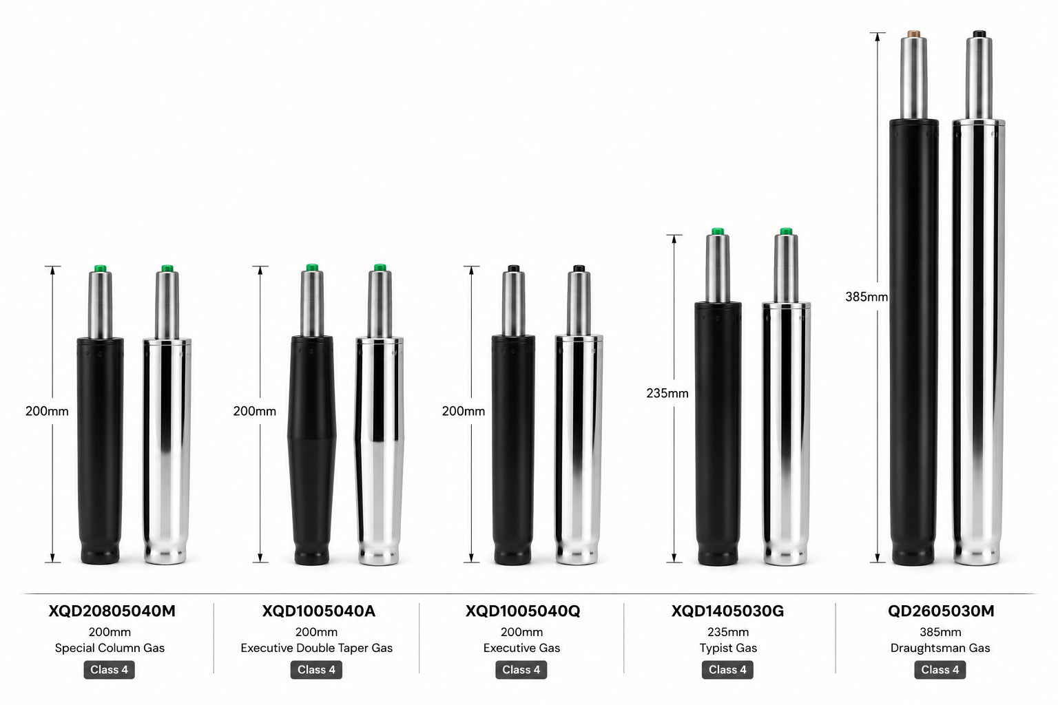
The Typist Cylinder — Trade Code 12/0
Commonly designated as a "235 mm cylinder" in assembly environments, the verified engineering specification shows a physical outer standpipe measuring 50 mm × 230 mm. This cylinder operates with a nominal stroke of 132 mm, achieving a total extended length of 427 mm. Fits low-profile task seating.
The Executive Cylinder — Trade Codes 13/0 and 14/0
These cylinders feature a 200 mm outer standpipe optimised for multi-function, swivel-tilt, and synchronous mechanisms. They provide a shorter 100 mm to 120 mm travel stroke, which offsets the taller stack height of these complex under-seat gear housings.
The Draughtsman Cylinder — Trade Code 15/0
While referred to as a "385 mm model" in generic documentation, verified catalogue data shows a standpipe length of 315 mm combined with a high guide-sleeve extension. This yields a 190 mm stroke and an extended length of 575 mm, which matches elevated counter-height stools.
2. Cylinder Classification (Class 1 – 4)
Understanding the structural differences in cylinder wall thickness is critical to preventing mechanical failure. The industry standard utilises a distinct Class rating scale:
| Class | Outer wall | Inner piston | Max static weight | Service lifespan & performance |
|---|---|---|---|---|
| Class 1 | 1.0 mm | 1.0 mm | Under 80 kg (176 lbs) | Basic, short-term usage; susceptible to deformation under lateral impact. |
| Class 2 | 1.0 – 1.2 mm | 1.5 mm | 100 kg (220 lbs) | Budget domestic seating; high rate of pressure-seal degradation over 20 000 cycles. |
| Class 3 | 1.2 mm | 2.0 mm | 120 – 150 kg (264 – 330 lbs) | Entry-to-mid-tier office chairs; retains pressure for ~30 000 – 50 000 cycles. |
| Class 4 | 2.0 mm+ | 2.0 mm+ | 200 – 250 kg (440 – 550 lbs) | Standard commercial seating; nitrided steel construction rated for 100 000+ compressions. |
Class 4 cylinders are manufactured using high-carbon, precision cold-drawn seamless steel tubes. This construction avoids the structural vulnerabilities of welded alternatives, which are prone to microscopic nitrogen-gas leaks and physical bending under shock loads.
Furthermore, high-grade Class 4 cylinders receive advanced gas-nitriding heat treatments to achieve a surface hardness exceeding HV600. This is combined with electroplating that withstands 120 hours of salt-spray testing to prevent corrosion in humid environments.
For any commercial seating job in KwaZulu-Natal, I only fit Class 4. The cost difference is roughly R80–R120 per cylinder — a non-event compared to the call-out cost of replacing a failed Class 2 cylinder six months later.
3. Deep Ergonomic Science & Structural Relationships
The mechanical layout of a chair can be modelled as a series of connected structural elements. Each component directly affects the physical force distribution and the height profile of the seating unit.
+---------------------------------------+
|          SEAT PLYWOOD FRAME           |
+---------------------------------------+
                   ||
+------------------++-------------------+
|       UNDER-SEAT CONTROL CHASSIS      |
|         (Stack Height, H_stack)       |
+---------------------------------------+
                   ||
+------------------++-------------------+
|        GAS CYLINDER PISTON ROD        |
|         (Adjustable Stroke, C)        |
+---------------------------------------+
                   ||
+------------------++-------------------+
|       STANDPIPE BODY COLUMN (L)       |
+---------------------------------------+
                   ||
+------------------++-------------------+
|       BASE COLLAR INSERT ZONE         |
|        (Collar Height, L_collar)      |
+---------------------------------------+
                   ||
+------------------++-------------------+
|          FIVE-STAR WHEEL BASE         |
|         (Hub Height, H_hub)           |
+---------------------------------------+
                   ||
            (Floor Level)
Fig 3.1 — Vertical stack of a complete office chair showing all height-contributing components.
The stack height (Hstack) of the under-seat control chassis is determined by its mechanical complexity. A basic, non-tilting swivel plate (Trade Code 9) or a simple typist mechanism (Trade Code 87) sits flat against the seat plywood, adding minimal vertical height.
In contrast, synchronised tilt mechanisms (Trade Code 11 or Donati Epron Plus Code 207) incorporate complex linkages, recline locks, and adjustable coil-tension springs. These components require a deep physical housing, which increases the stack height.
When a high-stack-height mechanism is paired with a standard cylinder, the default seating position can be too tall for shorter users. This mismatch leads to poor ergonomic posturing. If the user's feet cannot rest flat on the floor, their body weight concentrates on the underside of the thighs. This localised pressure can compress the popliteal artery and sciatic nerve — causing numbness, fatigue, and lower-extremity swelling.
4. Base Geometry & Floor Clearance
The architecture of the five-star wheel base directly impacts the positioning of the gas cylinder.
Standard bases feature a low-profile centre hub where the cylinder sits deep inside the collar. This configuration positions the bottom of the cylinder standpipe close to the floor while maintaining safe clearance.
STANDARD BASE CONFIGURATION              HIGH-ARCH SPIDER BASE CONFIGURATION
===========================              ===================================

   +-------------------+                    +-------------------+
   | Cylinder Standpipe|                    | Cylinder Standpipe|
   +---------+---------+                    +---------+---------+
             |                                        |
        /====+====\                              /====+====\
       /           \                            /  /===== \ \  <-- High Arch
      /   Low Hub   \                          /  /  Hub   \ \
     |               |                        |  |         |  |
     +-------+-------+                        +--+----+----+--+
             |                                        |  <--- Double taper locks
             |  <--- Standpipe drops                  |       cylinder higher up,
             |       close to floor                           maintaining clearance
Fig 4.1 — Side-by-side comparison: standard low-profile hub vs. high-arch spider hub.
Conversely, high-arch "spider" bases (such as Trade Code 120 or Code 625) sweep upward from the casters toward an elevated centre collar. If a standard single-taper cylinder is placed in a high-arch base, it will slip too far down through the elevated collar. This causes the bottom of the cylinder standpipe to drag along the floor, scratching surfaces and preventing the chair from rolling smoothly.
To prevent this floor interference, engineers use Double Taper (Trade Code 13/0) or Super Double Taper (Trade Code 16/0) gas cylinders. These cylinders feature a stepped taper profile machined onto the bottom of the 50 mm standpipe. This profile acts as a physical shoulder, locking the cylinder higher up within the elevated hub of the spider base. This design ensures the necessary floor clearance while maintaining structural stability.
5. The Master DIY Direct-Match Compatibility Directory
To simplify part identification for refurbishment projects, the following database maps the relationships between replacement part names, design types, commercial part codes, and physical configurations.
| Component | Trade code | Compatible seating models | Mechanism partner | Base partner |
|---|---|---|---|---|
| Typist Gas — Class 4 | Code 12/0 | Cancun Typist, Kelso Typist, 3050 Dental | Typist Mech (Code 87) | Standard Nylon (Code 620) |
| Exec Single Taper — Class 4 | Code 14/0 | Fire High-Back, Salvador Poly, Skye Executive | Swivel & Tilt (Code 91) | Lazio Chrome (Code 403) |
| Exec Double Taper — Class 4 | Code 13/0 | Adda Wooden, Premium Ergonomic | Roma Synchro (Code 11) | Mercury Alu Spider (Code 120) |
| Exec Super Double Taper — Class 4 | Code 16/0 | Heavy-Duty Synchro | Donati Epron (Code 207) | Donati Spider (Code 625) |
| Draughtsman Gas — Class 4 | Code 15/0 | Lenny Chrome, 3059 Dental | Swivel Plate (Code 9) | Loria Glides (Code 640) |
6. Visual Field Identification Guide
Because many DIY repairs involve working with worn parts that no longer have legible labelling, the following visual descriptions can be used to identify components and match them to replacement parts.
+-------------------------------------------------------------+
|             VISUAL FIELD IDENTIFICATION GUIDE               |
+-------------------------------------------------------------+
|                                                             |
|  TYPIST CYLINDER (Code 12/0):                               |
|     |||||||  ============================                   |
|  - Extended overall profile with single continuous taper.   |
|                                                             |
|  EXECUTIVE CYLINDER (Code 14/0):                            |
|     |||||  ===================                              |
|  - Shorter body; clean taper at base.                       |
|                                                             |
|  DOUBLE TAPER CYLINDER (Code 13/0):                         |
|     |||||  ============== ===/                              |
|  - Stepped, dual-diameter reduction at the bottom.          |
|                                                             |
|  DRAUGHTSMAN CYLINDER (Code 15/0):                          |
|     |||||||||||  ===================== O                    |
|  - Long standpipe, includes circular footring sleeve.       |
|                                                             |
+-------------------------------------------------------------+
Fig 6.1 — Side profile silhouettes for the four major cylinder families.
7. Spare Part Image Specifications
7.1 Typist Gas Cylinder (Code 12/0)
Physical features: Side-profile photo showing a continuous 230 mm matte-black standpipe. The upper piston rod is chrome-plated and features an orange-tipped valve activation button. The base features a gradual taper with no steps or shoulders.
Dimensions to verify: 50 mm diameter outer tube · 28 mm diameter piston tube · standpipe length ≈ 230 mm.
7.2 Executive Single Taper Cylinder (Code 14/0)
Physical features: Short 200 mm standpipe, typically finished in semi-gloss black paint or polished chrome. The lower portion tapers gradually over the final 30 mm, designed to insert deep into standard wheel bases.
Dimensions to verify: 50 mm outer tube diameter · 200 mm standpipe body length · standard 28 mm top taper.
7.3 Executive Double Taper Cylinder (Code 13/0)
Physical features: High-resolution photo focusing on the bottom 50 mm of the cylinder standpipe. The metal tube steps down in diameter twice, creating a shoulder that prevents the cylinder from dropping through high-arch base hubs.
Dimensions to verify: 200 mm standpipe length · look for a distinct change in tube diameter near the bottom taper.
7.4 Draughtsman Gas Cylinder (Code 15/0)
Physical features: Portrait-orientation photo showing an extended 315 mm standpipe. The cylinder is pictured alongside a circular chrome footring, which clamps onto the outer tube using a hand-tightening knob.
Dimensions to verify: 315 mm standpipe length · 190 mm stroke length · overall extended length of 575 mm.
7.5 Typist Mechanism (Code 87)
Physical features: Low-profile, flat-stamped steel mounting plate. The plate features a single lever on the right side for gas-lift activation and a second lever on the left to control the backrest angle.
Dimensions to verify: Standard mounting hole-slot spacing (typically 150 mm × 200 mm) · low profile · stack height under 35 mm.
7.6 Swivel & Tilt Mechanism (Code 91 / Palermo)
Physical features: Rectangular steel control housing with a large, cylindrical hand-tension adjustment knob extending downward from the front edge. A single metal control handle extends from the side to activate both height adjustment and tilt locking.
Dimensions to verify: High profile · stack height approximately 75 mm – 95 mm.
7.7 Roma Synchro Mechanism (Code 11)
Physical features: Heavy-duty cast-aluminium and steel housing, which contains internal gear plates and tension control springs. The unit features two or three independent paddle levers that control seat height, backrest recline tension, and tilt locking.
Dimensions to verify: Heavy physical construction · stack height exceeding 100 mm.
8. Seating Ergonomics & Geometric Height Formulas
Configuring a custom chair layout or specifying replacement parts relies on a series of geometric calculations. This ensures the chair's range of adjustment matches standard desk heights and fits the target user.
+------------------------------------------------+
|             HEIGHT DIMENSION SCHEMATIC         |
+------------------------------------------------+
|                                                |
|          =================================    |
|          |  Mechanism Stack Height (H_s) |    |
|          =================================    |
|                           |                   |
|                    +--------------+           |
|                    |  Piston (C)  |           |
|                    +--------------+           |
|                           |                   |
|          =================================    |
|          |   Standpipe Body Length (L)   |    |
|          =================================    |
|                           |                   |
|                     /=========== \            |
|                    /  Base Hub    \           |
|                   /  Height (H_b)  \          |
|                  /__________________\         |
|                      |          |             |
|                     (O)        (O) <-- Wheels |
+------------------------------------------------+
The minimum seating height (Hmin), measured from the floor to the top of the seat-pan cushion, is calculated using the following formula:
The maximum seating height (Hmax) is calculated by adding the cylinder's stroke length to the minimum height:
- Hhub
- Vertical height of the five-star base hub, measured from the floor to the top of the centre insert collar.
- Lstandpipe
- Overall physical length of the cylinder's outer standpipe body.
- Lcollar
- Depth of the cylinder's insertion inside the base hub collar before it locks.
- Hstack
- Vertical stack height of the under-seat control mechanism chassis.
- Cstroke
- Maximum extension (travel range) of the gas cylinder's piston rod.
9. Mathematical Analysis of Floor Clearance
To prevent a cylinder from dragging on the floor when paired with a high-arch base, the ground clearance (GC) of the standpipe's bottom must remain positive (GC > 25 mm for safety on thick carpets or uneven surfaces). Ground clearance is modelled by the following equation:
Example A — Standard base with single-taper cylinder
If Hhub = 90 mm, Lstandpipe = 200 mm, and the standard taper allows insertion depth Lcollar = 80 mm, the ground clearance is:
Example B — High-arch spider base with double-taper cylinder
If a high-arch spider base is used (Hhub = 140 mm) and paired with a double-taper cylinder (Code 13/0), the stepped taper stops the insertion earlier (Lcollar = 40 mm). The resulting ground clearance is:
10. Step-by-Step DIY Replacement & Maintenance Protocol
Replacing a gas-lift cylinder is a straightforward mechanical process. However, because these components wedge together under high pressure, standard disassembly often requires specific techniques to break the friction lock.
+---------------------------------------+
|  Step 1: Lubrication & Setup          |
|  Apply penetrating oil to both joints;|
|  let sit for 10-15 minutes.           |
+-------------------+-------------------+
                    |
                    v
+---------------------------------------+
|  Step 2: Base Disassembly             |
|  Strike base collar with rubber       |
|  mallet; separate base from column.   |
+-------------------+-------------------+
                    |
                    v
+---------------------------------------+
|  Step 3: Cylinder Extraction          |
|  Grip standpipe with pipe wrench;     |
|  twist firmly to break friction lock. |
+-------------------+-------------------+
                    |
                    v
+---------------------------------------+
|  Step 4: Reassembly & Locking         |
|  Drop new cylinder into base; drop    |
|  seat onto piston and sit to lock.    |
+---------------------------------------+
Pre-Assembly Inspection & Safety
- Ensure that the target workspace is flat, clean, and free of debris.
- Confirm that the replacement gas lift is of Class 4 construction.
- Avoid using steel hammers directly on the cylinder housing or the seat mechanism. High-velocity impacts can crack cast-aluminium housings or dent the cylinder standpipe, making it impossible to remove.
Step 1 — Joint Lubrication
Lay a protective cloth or piece of cardboard on the floor to catch any oil or grease. Flip the chair upside down. Apply a generous amount of penetrating oil (such as WD-40) to the lower standpipe joint at the wheel-base hub and the upper piston joint at the seat-mechanism plate. Allow the oil to penetrate the joints for 10 – 15 minutes to help loosen rust and dirt.
Step 2 — Base Removal
Hold the wheel base firmly with one hand while using a heavy-duty rubber mallet or brass-faced hammer in the other. Strike the central collar on the underside of the wheel base in a downward, circular pattern. These radial impacts create vibration waves that break the friction lock between the cylinder's 50 mm outer standpipe and the base hub taper. The wheel base will slide off the cylinder.
Step 3 — Cylinder Extraction from Seating Mechanism
Grasp the outer standpipe of the cylinder with a heavy-duty pipe wrench. Ensure the wrench jaws clamp onto the upper third of the outer standpipe, close to the seat plate.
Do not clamp the sliding chrome-plated piston rod. Scratches on the piston surface can tear the internal rubber seals, leading to pressure loss and cylinder failure.
Rotate the pipe wrench with a firm, continuous twisting motion. This torsional force shears the friction lock between the 17-4 piston taper and the mechanism plate's receiving sleeve, allowing the cylinder to slide free.
Step 4 — Component Reassembly & Locking
Place the five-star wheel base flat on the floor. Insert the tapered bottom of the new Class 4 cylinder (50 mm standpipe end) directly into the base hub. Press down firmly.
Align the seat-control mechanism sleeve over the top of the chrome piston rod (28 mm end) and lower the seat assembly into place. Sit on the chair and apply your body weight. This downward force wedges the tapered joints together, securing the assembly without the need for fasteners.
11. Technical Conclusions & Refurbishment Advice
To ensure safety and reliability in contract seating or individual DIY repairs, configurations must be designed to meet industry testing standards, such as ANSI/BIFMA X5.1 or EN 1335. These standards evaluate dynamic cycle endurance, lateral stability, and structural weight capacities under load.
Prioritise High-Grade Seals
Always specify Class 4 gas-lift cylinders for commercial repairs. The extra cost of Class 4 nitrided and seamless steel cylinders is offset by their safety, longer lifespan, and resistance to seal degradation.
Match Stack Heights Carefully
When replacing a low-profile typist mechanism with a synchronised tilt mechanism, you must swap out the cylinder as well. Failing to balance mechanism stack heights with the correct standpipe length will result in an incorrect seat-height range, leading to physical discomfort and poor posture.
Confirm Base & Cylinder Compatibility
Always check the shape of the five-star base before ordering replacement parts. Standard low-profile bases accept standard single-taper cylinders. However, high-arch spider bases require double-taper or super double-taper cylinders to maintain proper floor clearance and prevent dragging. Ensure these components are matched correctly to guarantee stable and reliable seating.
Not sure which cylinder fits your chair?
Send me a photo of the underside of your chair on WhatsApp and I’ll identify the correct trade code and quote you the right Class 4 replacement. Nationwide delivery, rate calculated at checkout.
📲 Get a Quote