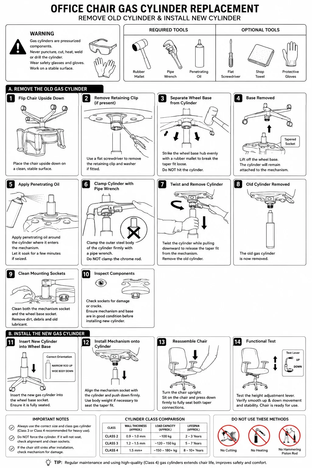
Professional Instruction Manual Image Set
Correct Technical Procedure (Commercial Repair Standard)
A proper office chair gas cylinder replacement is not just “pull and replace.”
The cylinder is held in place by a friction taper fit at two connection points:
- Top taper fit → chair mechanism plate
- Bottom taper fit → five-star wheel base
There are no screws or threads on standard office chair gas lifts.
The safest and most accurate removal method is:
- Separate base from cylinder
- Separate mechanism from cylinder
- Install new cylinder using body weight compression
- Never puncture, heat, cut, or clamp the cylinder tube
This matters because office chair gas cylinders are pressurized pneumatic components.
Recommended Instruction Manual Image Set Structure
You should create this as a 10–12 panel monochrome technical line-art set.
Style:
- Black & white vector line drawing
- Minimal shading
- ISO/manual style
- Clean arrows
- Numbered sequence
- Consistent chair angle
- Tool icons
- Safety warning icons
COMPLETE PANEL BREAKDOWN
PAGE 1 — SAFETY + REQUIRED TOOLS
Panel 1 — Safety Warning
Show:
- Safety glasses
- Gloves
- Rubber mallet
- Pipe wrench
- Chair upside down
Text:
WARNING
Gas cylinders are pressurized components.
Never puncture, cut, heat, or drill the cylinder.
Panel 2 — Required Tools
Illustrate:
Required:
- Rubber mallet
- Pipe wrench
- Penetrating oil
Optional:
- Flat screwdriver
- Shop towel
- Protective gloves
Important:
Use realistic tool proportions.
PAGE 2 — REMOVE THE CHAIR BASE
Panel 3 — Flip Chair Upside Down
Illustration:
- Chair resting on seat/back
- Wheels facing upward
Arrow:
Rotation arrow showing flipping action.
Text:
Place chair upside down on a stable surface.
Panel 4 — Remove Retaining Clip (if present)
Deep research detail:
Some chairs use:
- Retaining clip
- Washer clip
- Push nut
Illustrate:
- Flat screwdriver prying retaining clip
Text:
Remove retaining clip and washer if fitted.
Panel 5 — Separate Wheel Base from Cylinder
CRITICAL ACCURACY DETAIL:
Correct removal:
- Strike around base hub with rubber mallet
- NOT the cylinder shaft itself
Illustration:
- Rubber mallet hitting underside hub
- Downward arrow on cylinder
Text:
Strike the wheel base hub evenly with a rubber mallet to release taper fit.
Panel 6 — Base Removed
Illustration:
- Base separated
- Cylinder still attached to mechanism
Important:
Show:
- Inner tapered socket
PAGE 3 — REMOVE CYLINDER FROM MECHANISM
Panel 7 — Apply Penetrating Oil
Illustration:
- Oil being sprayed where cylinder meets mechanism
Text:
Apply penetrating oil around taper connection if seized.
Panel 8 — Clamp Cylinder with Pipe Wrench
CRITICAL:
Wrench clamps:
- OUTER steel body only
- Never chrome piston rod
Illustration:
- Pipe wrench on lower cylinder tube
Text:
Clamp only the outer steel body of the cylinder.
Panel 9 — Twist and Remove Cylinder
Illustration:
- Rotational arrows
- Cylinder separating from mechanism
Text:
Twist firmly while pulling downward to release taper fit.
Important:
The mechanism remains stationary.
Panel 10 — Clean Mounting Sockets
Illustration:
- Cloth wiping sockets
Text:
Remove debris and old lubricant before installation.
PAGE 4 — INSTALL NEW CYLINDER
Panel 11 — Insert New Cylinder into Base
Illustration:
- Cylinder inserted into star base
Important:
- Narrow piston upward
- Wide body downward
Text:
Insert new gas cylinder into wheel base socket.
Panel 12 — Install Mechanism onto Cylinder
Illustration:
- Mechanism lowering onto cylinder
Arrow:
Downward force arrows.
Text:
Align mechanism and press firmly into taper fit.
Panel 13 — Reassemble Chair
Illustration:
- Chair upright
- Person pressing down while seated
Text:
Sit on chair to fully seat taper connections.
Panel 14 — Functional Test
Illustration:
- Up/down arrows
- Height lever operation
Text:
Test height adjustment and stability before use.
IMPORTANT TECHNICAL ACCURACY NOTES
Correct Cylinder Orientation
Must show:
- Chrome piston rod UP
- Large body DOWN
Many inaccurate manuals get this wrong.
Correct Removal Force
Correct:
- Shock force on hub
- Rotational release on cylinder body
Incorrect:
- Hammering piston rod
- Heating cylinder
- Cutting cylinder
Correct Tool Use
Pipe wrench:
- ONLY on outer steel tube
Never:
- On chrome rod
- On activation valve pin
VISUAL DESIGN SPECIFICATIONS
Style
Use:
- Technical line art
- Service manual aesthetic
- Exploded diagrams where helpful
Avoid:
- Cartoon styling
- Photorealism
- Color-heavy visuals
IDEAL OUTPUT FORMAT
Best Deliverables
1. Print Manual
- A4 portrait
- 300 DPI
- Vector-style
2. Web Version
- Long vertical infographic
- Mobile readable
3. Individual Panels
Useful for:
- Google Business posts
- Facebook carousels
- Website tutorials
- WhatsApp support
SEO / COMMERCIAL VALUE
This content is extremely valuable because it positions Bizniz Chairs as:
- Technical experts
- Commercial repair specialists
- Safety-conscious professionals
- Upgrade-focused service providers
Especially when paired with:
- Your Class 4 cylinder messaging
- “We don’t just repair, we upgrade” positioning
Recommended Extra Technical Panels
Optional advanced panels:
“Cylinder Types Comparison”
Show:
- Class 2 vs Class 4 wall thickness
- Weight ratings
- Lifespan comparison
“Common Failure Symptoms”
Show:
- Chair sinking
- Sticking
- Leaning
- Sudden drop
“Incorrect Repair Methods”
Show:
- Red X over:
- Angle grinder
- Blowtorch
- Hammering piston rod
These dramatically increase authority and educational value.